Mining in Manitoba
Geophysical Methods
Seismic Surveys
|
|
Seismic methods have little use in metalliferous exploration because of the relatively small size and complicated geology of the typical ore deposit, and because of the high cost of seismic work. The method depends upon the velocities of acoustical energy in earth materials, and has been enormously successful in searching for petroleum, natural gas, and sulfur, where the large deposits may be located by simply determining attitude of the enclosing strata.
In engineering and hydrogeology, seismic refraction has many applications. Often, bedrock structure and topography control contaminant migration. Seismic refraction is a valuable tool for mapping bedrock troughs and fractures. It is usually more cost-effective and gives better coverage than drilling alone.
Constraints: Layer velocity (density) must increase with depth. Layers must be of sufficient thickness to be detectable. Data collected directly over loose fill (landfills) or in the presence of excessive cultural noise will result in sub-standard results. Single narrow fractures are too small to be detected.
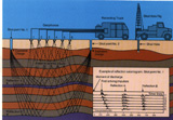
Method: The seismic refraction method utilizes sound waves. Sound travels at different velocities though different materials and is refracted at layer interfaces.
A seismic wave is usually generated by a small explosive charge, a shotgun shell, or a sledge hammer. The wave's travel time from the sound source to refracting layers, along those layers and back to detectors (called geophones) is precisely measured. From the time-distance relationships, subsurface layer velocities and thicknesses can be calculated.
Fracture zones can often be detected because they usually have a lower seismic velocity than solid bedrock. The velocity of sound through water saturated material is about 5000 feet per second while the velocity though crystalline bedrock generally ranges from 12,000 to 18,000 feet per second. By calculating the velocity of sound along the bedrock surface, low velocity zones, which may represent fractures, can be delineated.
Some systems utilizes up to 24 geophones at one time. The geophones can be linearly spaced any distance apart, but most often are spaced 10 to 50 feet apart. In general, the greater the expected bedrock depth, the greater the geophone spacing. Shorter spacings and sometimes radial patterns are used in fracture zone detection studies.
Both 12- and 24 channel seismographs are used in the field. The 24-channel instrument has an internal computer. Seismic field data are stored on 3.5 inch disks for later computer analysis.
Final results are provided to the client in a full report which includes tables of
subsurface depths and elevations, and cross-section profiles. Results are also available
as bedrock contour maps and on computer disks.
Seismic Reflection
- graphically depicts subsurface stratigraphy and bedrock profiles
- can often differentiate unconsolidated units such as sand, clay, or gravel
- marine surveys
Seismic reflection is useful for graphically profiling subsurface stratigraphy. It is used to map clay and sand lenses and bedrock troughs. Applications of this technique include determination of depth to bedrock, aquifer location studies, and mapping of overburden stratigraphy.
Constraints: Reflection surveys are highly site specific. A shallow ground water table is required. Reflection surveys are useful for exploration depths of 50 feet to several hundred feet.
Method: Seismic reflection is a geophysical technique in which acoustic waves, reflected directly from underground surfaces with density contrasts, are used to map soil and bedrock stratigraphy.
Successful application depends upon the ability of the ground to transmit high frequency seismic energy (saturated clays, for example, transmit high frequency energy quite well). The method overcomes some of the potential problems encountered in refraction surveys (such as the assumption that subsurface layer velocities increase with depth and that layers are thick enough to be detectable).
The equipment used is nearly identical to that used in a seismic refraction survey. The field technique, however, differs and ground coverage is usually slower than with a refraction survey.
The client is provided with a full report, including graphic profiles of subsurface structures.